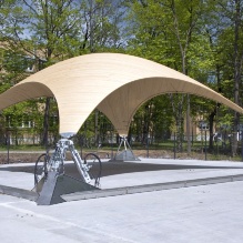
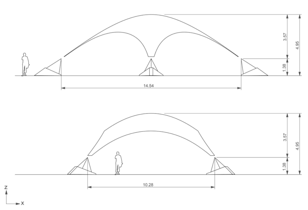
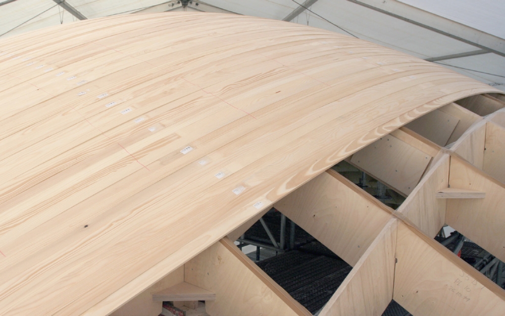
The Stuttgart SmartShell is the world’s first full-scale prototype of an adaptive shell structure. Spanning an area of 10 m x 10 m with a thickness of only 40 mm, the structure is the culmination of research into adaptive ultralightweight structures conducted by the Institute for Lightweight Structures and Conceptual Design (ILEK) and the Institute for System Dynamics (ISYS) of the University of Stuttgart. Much thinner than previously conceived possible, the structure is able to resist effects of static and dynamic loading through the active manipulation of its support points, reducing stresses and vibrations. The construction of the prototype was accomplished in cooperation with Bosch Rexroth.

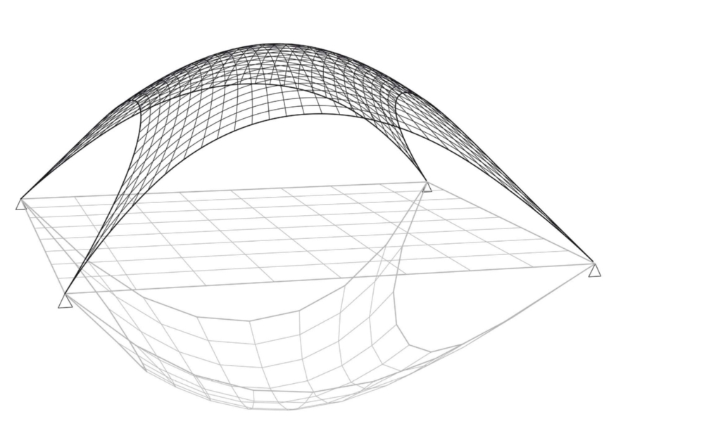
The initial geometry was determined using form-finding methods simulating a hanging net under even loading. Such methods can approximate ideal geometries, however, optimal structural response can only be achieved for the form-finding load case. In ultralightweight structures, inhomogeneous stress distributions and vibrations caused by environmental loads, are compensated through the use of active components.

PRODUCTION OF THE WOODEN SHELL
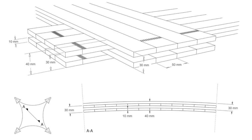
The shell construction comprises a four-layer system of cross-laminated timber. Each layer consists of 10 mm thick wooden slats (type spruce-fir) with adjacent layers having orthogonal wood fiber directions. The resulting structural system can be described as a “double-sandwich” with two main load bearing directions, each of which is aligned diagonally between opposite supports. To determine the cutting patterns, scripts written in Rhinoceros and Rhinoscript® translated the double-curved surface into single-curved slat elements. To reduce the complexity during fabrication and handling, a simplification algorithm grouped similar cutting patterns and modified their geometries to make them identical. Thus, the number of cutting patterns and correspondingly the number of mill paths were reduced to 6. The maximum width of the slats is set at 50 mm, resulting in elements tapering down to 16 mm at the supports for the longest pieces, spanning 16 m diagonally between opposite supports.
The slats are fabricated in segments with a length of 3 m and were then connected using finger joints to arrive at the overall lengths. By alternating the direction of adjacent slat elements, the location of the finger joints are thus offset by one half of the element lengths between adjoining slats. The 3 m segments of the slats were fabricated according to the cutting patterns using a CNC mill. A special clamping device securely positions the slats during the milling process. This device permits the simultaneous processing of 24 slats with one mill path, while assuring fabrication tolerances within ±0.2 mm for the milled segments. The shell structure contains approximately 8000 m of milled slat segments.
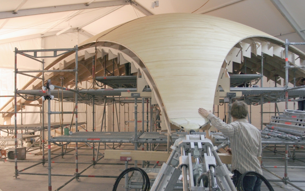
CONSTRUCTION
A concrete experimental platform was constructed adjacent to the ILEK institute building to facilitate the erection of the prototype. A temporary tent structure was built to ensure adequate environmental protection during the construction process (including heating and humidity control as required for the structural wood adhesive).
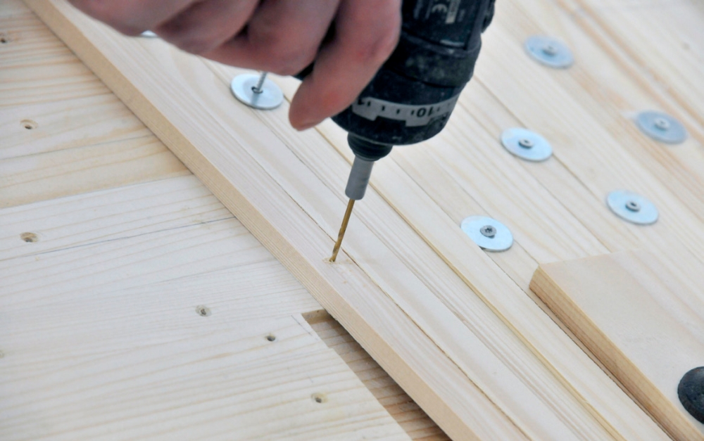
To facilitate the construction of the shell, a grid-type substructure to control the geometry was first fabricated using a CNC mill and then erected. The plywood grid elements (18 mm thickness) with a height of 300 mm were spaced at 523 mm and supported on scaffolding at a spacing of 1.57 m. Then, the slat segments of the first layer were affixed to the substructure using screws to facilitate removal of the substructure upon completion of the shell. Each subsequent layer was joined to the previous layer using a polyurethane adhesive. Screws were used during the initial installation to provide adequate curing pressure and were removed upon hardening of the adhesive. Upon completion of the last layer, the finishing steps included milling of the edges, sanding, and applying wood stain for environmental protection.
In a parallel process, the mechanical components for the supports and hydraulic system were installed. As a final step of the construction process, the support structure and the shell were joined immediately prior to lowering the substructure, to be followed by the finishing work of the bottom surface and the installation of strain sensors.
ACTIVE COMPONENTS
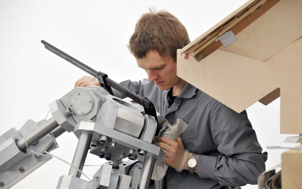
The actuation of the supports is realized by a Bosch Rexroth hydraulic system. The system includes nine 300 mm cylinders that are used to actuate the tripods. The cylinders are equipped with high-precision position sensors and pressure gages, which allow the measurement of the cylinder force up to the maximum force of about 50 kN. High-speed control valves are used to deliver pressurised hydraulic oil in the cylinder chambers to generate a force output.
PROJECT PARTNERS
Institute for Lightweight Structures and Conceptual Design
Prof. Dr.-Ing. Dr. Ing. E.h. Werner Sobek
Dr.-Ing. Walter Haase
Institute for System Dynamics
Univ.-Prof. Dr.-Ing. Oliver Sawodny
Dr.-Ing. Eckhard Arnold
Project Management, Structural Engineering
M.Eng. Stefan Neuhäuser
Project Management, Dynamics and Control Systems
Dipl.-Ing. Martin Weickgenannt
Architectural Design, Digital Fabrication and Construction Process
Dipl.-Ing. Christoph Witte
Mechanical and Electrical Engineering
Dipl.-Ing. Christoph Göhrle
Dipl.-Ing. Joachim Endler
Mechanical Component Fabrication
Peter Bachhuber
Markus Berndt
Jürgen Braig
INDUSTRY PARTNERS
Bosch Rexroth AG
The Drive & Control Company
Project Management
Dr.-Ing. Johannes Grobe
Dipl.-Ing. (DH) Dipl.-Ing. (DH) André Fella
Hydraulic Control Technology
Dipl.-Ing. (FH) Edgar Holembowski
RESEARCH FUNDING
German Research Foundation (DFG)
CONSULTING
Valuable assistance during the design of the prototype was provided by Prof. Dr.-Ing. Leander Bathon (Hochschule RheinMain, MPA Wiesbaden, Institut für Baustoffe und Konstruktion). Wood fabrication was performed with the generous support of Prof. Dr.-Ing. Prof. E.h. Dr. h.c. mult. Uwe Heisel and Dr.-Ing. Marco Schneider (University of Stuttgart, Institute for Machine Tools) and Andreas Hauke (University of Stuttgart, Wood fabrication shop).
SPONSORS
The realization of the prototype was made possible with the help of the following: Bosch Rexroth AG, Eschenbach Zeltbau GmbH & Co. KG, Leitz GmbH & Co. KG, Ulrich Lübbert Warenhandel GmbH & Co. KG, RÜTGERS Organics GmbH, Sensor-Technik Wiedemannn GmbH, Holzwerk Friedrich Wahl GmbH & Co. KG, Wilhelm Gerüstbau GmbH.
CONSTRUCTION SUPPORT
Simon Alt, Christian Assenbaum, Markus Aydt, Frank Bender, Christian Bergmann, Johanna Breitenbach, Manuela Brüggeboes, Jonathan Busse, Marvin Bux, Yilmaz Demir, Jürgen Denonville, Anne-Carolin Döhmel, Tobias Edelmann, Jan El Hussein, Franz Falkenau, Dominik Felix, Christine Flaig, Clemens Freitag, Oliver Gericke, Janis Großmann, Malte Gröner, Axel Guse, Ilse Guy, Stefan Hans, Johannes Hasselhoff, Benjamin Henke, Jürgen Hennicke, Gunter Heppeler, Michael Herrmann, Oliver Hesse, Corina Hommel, Marco Houchmand, Susanne Hügel, Marzena Husser, Sebastian Husser, Dennis Kasper, Alexander Keck, Thorsten Klaus, Lukas Knierim, David Knies, Simon Köppl, Valerie von Koerber, Holger Kurz, Christian Kvalsund, Martin Lahr, Philipp Längst , Sophia Leistner, Alexander Lutz, Tobias Mahl, Florian Malchow, Gabriela Metzger, Jan Mittelstädt, Andreas Moog, Heiko Müllerschön, Friederike Musselmann, Zied Ouerdiane, Alexander Pertsch, Markus Plank, Justin Pradipta, Gerlind Preisenhammer, Sven Priestaff, Marijo Prskalo, Andreas Pritschow, Kerstin Puller, Philipp Rapp, Markus Richter, Thomas Ruppel, Hélène Schloter, Fabian Schmid, Benjamin Schuler, Marcus Sonntag, Johannes Störkle, Jay Wagenpfeil, Mark Wörner, Evelina Zapala, Michael Zeitz